According to this calculator it should be possible to build a 5 resonator interdigital filter at 2 GHz with acceptable loss and narrow enough so I decided to build it. As I have no access to a machine shop I followed the construction proposed on another web site and using the square tube and the input/output antenna's from the later and I build the calculated filter from the first link.
Result is a 5 resonator interdigital filter in a square aluminium tube with solid copper resonators as can be seen in this picture
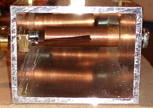
You can just see the input antenna and two copper resonators with their tuning screws
The only special tool I used was a 4mm wire tap for attaching the resonators and the tunng screws.
After building the real problem start. A filter of this order will not let anything through if not tuned correctly. I could not find how other people did this initial tuning so I created a field sensor as shown in this picture

It was small enough to be inserted from one side of the filter past all the untuned resonators till the resonator up for tuning so I could tune one resonator at a time.
The end result was a 2MHz 3db bandwith at 2.016Ghz and sufficient suppression at 20MHz offset to ommit my 110MHz IF.
This led to an updated SA with this block diagram

Short specs; 0-2GHz input, 0-30dB attenuator IP3 at +17dB with 0dB attenuator. Noise floor around -100dB with 300kHz bandwidth, 300/30kHz HW resolution filters and FFT resolution filters down to 1Hz. Almost no spurs.
You can see the full set of components in this picture

As the ADF4351 have two outputs I added a 3GHz bridge and a triple receiver so the HW doubles as a 35MHz till 3GHz VNA
The unmarked module at the left bottom is a third ADF4351 that can be used is mixed (0-2GHz) or direct (35MHz-2GHz) tracking generator
I hope this inspires more people to build their own GHz cavity filters
Geen opmerkingen:
Een reactie posten